 Lamination is a process used in many sectors such as paper processing, packaging, construction and reinforced plastics amongst others. Laminators tend to differ from one another so broad ranging yet expert control knowledge is a necessity when upgrading a laminating line. Below you can find control system descriptions of several projects completed by Optima for laminating lines. Optima’s experts are well familiar with the working principles of a laminating line as it is demonstrated below.
Machine philosophy
General
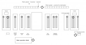
The machine unwinds board from a dual spindle flying splice unwind stand. The board passes over an existing steering unit, passes through a Pulling Unit and to the Laminator. The Laminator is the line speed master. The film is unwound from an existing unwind unit and is then driven through an adhesive unit and then an oven before being laminated with the board. The laminated board passes over the Delaminator where the film can be stripped from the board. If the film is delaminated from the board it passes through a Pulling unit and then on to a Film rewind. From the Delaminator the board passes on to the lacquer unit and then on to the Rewind pulling unit and the dual spindle flying splice rewind. Parts of the machine have the ability to operate in both draw and closed loop tension control.
Board Unwind
The two unwind spindles operate in closed loop centre wind with dancer position control. The required tension is entered via the HMI and is controlled by a I/P converter mounted in the junction box. Both a manual and automatic splicing function are available on the unwind. The splice arm only operates in under-wind mode. Splicing is initiated from the operator panel. There are also operator controls to run brush motor and for manual control of the unwind. During automatic splice the unwinds are turreted into an initial position using an AC motor. This position is detected using a proximity sensor mounted on the fixed unwind stand and a counter is reset. The splice arm is raised into position and then the unwind is turreted until the photo cell mounted on the splice arm detected the incoming reel. A counter is used to count pulses produced by the encoder mounted on the turret and stops when the light beam is broken. This provides a method of calculating the diameter of the incoming reel so that the correct speed can be used for splicing. Once the splice is complete, initiated by a switch on the operator pendant, the outgoing reel is stopped and the splice arm is returned to its lower position. After the board has passed over the dancer unit it goes on to a steering unit which is not part of this refurbishment.
Board Unwind Pulling Unit
At the time of the site survey this unit was being bypassed. This unit operates in closed loop tension control with load cell feedback which are located immediately after the pulling unit nip. The required tension is entered via the HMI. There is the facility for this section to be deselected if it is not required.
Film Unwind
The Film unwind section is a relatively new unit. The existing controls be retained and interfaced with the new control system. There is the facility for this section to be deselected if it is not required.
Adhesive Unit – Ex Zone 1
This unit operates in either closed loop tension control with load cell feedback or in draw control. The load cells are mounted at the top of the oven following the adhesive unit. The required tension or draw ratio is entered via the HMI. There is the facility, to enter the roll diameter via the HMI, to accommodate different size cylinders. The oven has four fans which are selected from the operator panel.
Laminator
This unit is the line master. There is the facility, to enter the roll diameter via the HMI, to accommodate different size cylinders.
Delaminator
This unit operates in either closed loop tension control with load cell feedback or in draw control. The required tension or draw ratio is entered via the HMI. The load cells for this section are mounted just prior to the unit but it should be noted that the original web path drawing for the machine is very different from that being used with the web passing around the load cell roller in the opposite direction to that shown. There is the facility, to enter the roll diameter via the HMI, to accommodate different size cylinders. There is the facility for this section to be deselected if it is not required.
Film Rewind Pulling Unit
During the site survey this unit was not being used and the encoder was missing from the motor. This unit operates in closed loop tension control with load cell feedback. The load cells are mounted just prior to the pulling unit nip. The required tension is entered via the HMI. There is the facility for this section to be deselected if it is not required.
Film rewind
The two rewind spindles operate in closed loop centre wind with dancer position control. The required tension is entered via the HMI. There is the facility for this section to be deselected if it is not required.
Lacquer Unit – Ex Zone 1
This unit operates in either closed loop tension control with load cell feedback or in draw control. The load cells are mounted before the section above the Ex zone. The required tension or draw ratio be entered via the HMI. There is the facility, to enter the roll diameter via the HMI, to accommodate different size cylinders. There is the facility for this section to be deselected if it is not required. Once the board has been lacquered it passes through an oven. The oven fans can be started from the operator panel mounted on the end of the unit.
Board Rewind Pulling Unit
Once the board has been lacquered it passes through the oven and around a load cell roller and on to the Rewind pulling unit. This unit operates in closed loop tension control with load cell feedback. There is the facility, to enter the roll diameter via the HMI, to accommodate different size cylinders. There is the facility for this section to be deselected if it is not required.
Rewind Layon Roll
This unit operates in open loop torque control. The required torque is entered via the HMI.
Board Rewind
The two rewind spindles operate in closed loop centre wind with dancer position control. The required tension and taper tension is entered via the HMI and is controlled by a I/P converter mounted in the junction box. Both a manual and automatic splicing function is available on the rewind.The splice arm only operates in under-wind mode. Splicing is initiated from the operator panel. There are also operator controls for manual control of the rewind. During automatic splice the rewinds are turreted into position using an AC motor. This position is detected using a proximity sensor mounted on the fixed rewind stand. The splice arm is lowered into position so that it touches the incoming reel. The layon motor runs in torque control. Once the splice is complete the outgoing reel is stopped and the splice arm is returned to its upper position.
Projects
One laminator control system upgrade done by Optima featured installing two drives: Lower Track and Upper Track. The Lower Track Drive was the master. The line speed reference signal was derived from the potentiometer on the operators’ console. The drives were supplied via circuit breakers and also fitted with a brake resistor to eliminate excess regenerated energy during emergency stop. Both drives start and stop in response to a single signal provided by the pre-existing relay. The speed set point is switched between Line Speed and Manual Speed by a signal from the pre-existing relay. The direction of motion was selected by a signal from the pre-existing relay.
- Lower Track Drive. The Lower track drive operates as the speed master for the system and provides a torque signal to the Upper track drive.
- Upper Track Drive. The Upper Track Drive follows line speed with a correction from an internal PID loop to enable load sharing between the two drives based on the torque signal from the Lower Track Drive.
For another small project, a new Emergency Stop System was designed by Optima for a laminator to include emergency stop devices in locations such as:
- Unwind Reel stand
- Embosser Panel and Embosser
- Traction Rolls and Elevator Sections
- Coater in feed and access guard
- Sheeter
- Entrance to and exit from the laminator section
- The emergency stop system was constructed to suit category 2 / 3 where appropriate. When activated: drives are stopped as soon as possible and after a short time delay, the power is removed from the drives. A stop command is given to the machine control system and it is prevented from starting by interruption of the start command. An illuminated pushbutton (blue) indicates that the emergency stop system has been tripped and must be reset by pressing the button once the cause of the emergency stop has been removed. A blue indicator lamp indicates in which section a button has been pressed.
- In addition to the emergency stop system, a light guard system protects operators of the elevator section from trapping their feet. The light guard system prevents lowering / rising of the elevator while the light beam is broken. Once broken, the system must be reset manually by push button. A test push button is also provided to test the function of the light guard system without creating a dangerous situation. Opening the side access guard for pallet removal trips the light guard system and prevents elevator movement. Emergency Stop also trips the light guard system to prevent movement of the elevator.
Would you like to know more about other control system projects we have completed on laminating machines? Please, leave us a short message here and we will send you additional information within 24 hours!


