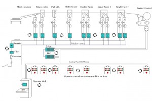
 Corrugated materials are widely used for packaging purposes as well as in sectors such as agriculture and electronics. Corrugating machines are, therefore, important assets for a large number of packaging companies. Optima has helped some of them by improving corrugators’ performance and reliability. The diagram below depicts the control system designed by Optima for one corrugating machine. Below you will also find descriptions of two upgrade projects completed by Optima’s experts.
This remote I/O system places suitable I/O hardware close to the actual pushbuttons/lamps on the corrugator machine sections. Doing so removes the necessity for a large number of hard wires to be run between the main machine and the control cubicles, only a single fieldbus communications cable is required. This together with an emergency stop and power supplies were the only small signal wires that would be required. This resulted in lower installation equipment and effort being required and consequently lower cost.
There was an extra cost associated with the remote I/O hardware but this often balances advantageously when set against the installation cost savings.
For another project, our proposal was that the nip roll had to be controlled in a similar fashion to speed control. We suggested that a closed loop vector drive be employed following the main motor encoder signal which would give a high accuracy control loop.
In this case, the option to employ torque control would cause potential problems associated with the mechanical arrangement, namely:
- The nip rolls have a limited amount of nip pressure that can be applied between them (to avoid crushing the corrugated material). This in turn means the amount of torque that can be applied to the nip rolls is also limited and determined by the frictional coefficient of the nip roll surface to the board, the nip pressure being a major factor in this.
We suggested that the resolution of the torque value required to run the arrangement in torque control would be very fine.
The gearbox between the input AC motor and the nip roll was a worm type box and has a ratio of 5:1. Furthermore, the gearbox was quite old.
Worm boxes are inefficient, new ones have typically 60% efficiency at max input speed and so have relatively high losses. This meant that a relatively large proportion of torque would be required to overcome these losses.
The gearbox ratio effectively multiplies the torque at the motor shaft reducing the resolution by the ratio value. In practical terms, the amount of torque required to tension the material might be small compared to that required to overcome losses. This let us to believe that employing torque control would be impractical due to the torque resolution.
By employing a closed loop vector drive and motor arrangement in encoder following mode, the system was a high accuracy one and could be adjusted to introduce more or less speed trim to control the draw on the material.
This method relied on the nip roll slipping (as they must do with a mechanical line shaft arrangement and over-speed).
Would you like to know more about other control system projects we have completed on corrugating machines? Please, email us at info@optimacs.com or call us on +44 (0)1254 27 28 29

