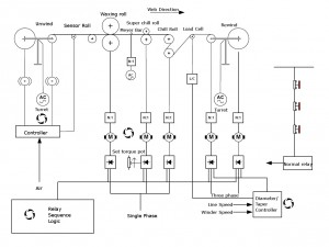
 Waxing machines are used for coating purposes in the packaging sector. Waxed paper, for example, is a popular packaging material. Optima have engineered a number of waxing machine upgrades. One particular project was very demanding due to the machine’s unreliability and high fault rates. The fundamental purpose of the machine remained unchanged. Our proposal addressed the problems experienced through poor sequencing of the control system, and the tension control issues in both the main wax roll area and the rewind area.
The waxing machine’s working principles are shortly described below (please, refer to the diagram):
Unwind
The unwind is a brake controlled unwind with a feedback medium and controller. It is a turretting unwind. It comprises a reversing contactor pair with an overload unit.
Waxing Roll
The waxing roll is a driven roll (master speed controller) with a manually applied nip roll. It is driven by a single phase, variable speed DC drive. The motor-gearbox is a Shunt wound DC motor coupled with a right angled worm and wheel gearbox.
Super Chill Roll
The super chill roll is a driven roll, controlled in open loop torque mode. It is driven by a single phase, variable speed DC drive. The motor gearbox is a shunt wound DC motor coupled to a right angled worm and wheel gearbox. The operator adjusts the tension (torque) on the motor by a ten turn potentiometer with a vernier dial.
Main Chill Roll
The main chill roll set is a driven roll operating in speed control. It is driven by a single phase variable speed DC drive. The motor gearbox is a shunt wound DC drive coupled to a right angled gearbox. The exact type could not be easily determined. The chill rolls allow the waxed paper to slip over their surface.
Rewind
The rewind is a manual turretting, torque controlled stand with manual splicing operation. The rewind spindles are controlled by single phase DC drives with automatic diameter compensation and taper control. The diameter compensation and taper functions are controlled by a single analogue system. The compensation system is changed over from spindle to spindle when a splice is performed.
The differences between the existing scheme and the proposed by Optima system are as follows:
Sequential relay logic replaced by the PLC
This provides the flexibility to allow timed and controlled sequencing of the control system elements to allow a controlled start up.
Three Phase Drives on the Rewind section
Three phase drives provide improved form factor for the drive/motor combination. This allows full tension range to be achieved without overheating the motors. The diameter/taper control unit is replaced by individual drive resident winder configurations (more sophistication and better control achieved).
A load cell is used to indicate the tension in the web prior to the rewind spindles.
From start up, the tension can be applied using a ‘soft start’ technique, so eliminating the web break problems at initial thread up stage.
Emergency Stop System
The emergency stop system is replaced with a compliant system to meet the requirements determined by your risk assessment.
Torque control of the Super Chill Roll
The tension in the waxing section is controlled by a shunt wound DC motor operating in torque control. The drive train comprises a 3000 rpm motor and right angled worm and wheel type gearbox. Worm boxes are not efficient and have relatively high mechanical losses. Losses for which the torque required to overcome them are significant when associated with the torque required to tension the web. This is evident to the operators who have less than 1% of a ten turn potentiometer and dial with which to control the section’s tension.
The torque control for this section is modified by monitoring the torque requirement of the machine during commissioning and setting this value on a potentiometer inside the control cubicle. A potentiometer mounted on the control cubicle has an additional torque trim of ± 10% over the full range of the potentiometer. This with the addition of a motor current meter allows the operators to set the motor torque more consistently.
Would you like to know more about other control system projects we have completed on waxing machines? Please, leave us a short message here and we will send you additional information within 24 hours!

