 Perforating machines find their application in a variety of manufacturing sectors – processing of paper, plastic film, steel and aluminium to name a few. Hot perforation is a preferred method for brittle substances such as plastic film. Optima has been involved in the design of a perforating machine control system. The machine was designed to perforate reels of film laminate using a combined heat and pressure process. To achieve this, the film is passed through a nip created between a heated perforating roller and a heated anvil roller. During the perforating process paper is used to protect the film from damage. The perforated film is slit into strips and each strip is then wound onto an individual reel.
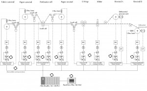
The schematic diagram below shows an overview of the control system designed by Optima for this perforating machine. An Allen Bradley SLC500 PLC controls the line. The PLC is networked using DeviceNet to Parker SSD 690+ inverter drives. The PLC is networked using DH-485 to an Allen Bradley PanelView Plus 700 touch screen operator panel and to a programming port on the control cabinet door. The film rewind, paper rewind, perforating roll, anvil roll, paper rewind, S wrap, slitter and product rewind motors are controlled by Parker SSD 690+ closed loop AC vector drives. The product rewinds use differential pressure shafts. Product rewind tension is controlled by the rewind drives via E-P converters.
Operator controls
Most operator control functions are carried out on the HMI located near to the perforating nip, additional pushbuttons and lamps are located on the unwind stand panel and the rewind stand panel.
Line operation
The temperature of the anvil and perforating rolls is controlled by a separate stand-alone system. The operator starts these rolls manually and they operate at a fixed idle speed. The rolls remain open until the line runs to prevent burning of the paper or film.
The unwind and rewind drives automatically compensate for reduction / build up of product on the reels. Diameter sensors located on the paper unwind, film unwind and paper rewind are used below 5% line-speed to preset the respective drives internal diameter calculation blocks. The product rewinds use the diameter sensor located on the product rewind A to compensate for diameter build up. Load-cells situated after the paper unwind, after the film unwind, before the paper rewind and after the S-wrap are used to provide feedback of actual web tension. When the perforating nip is open and the film unwind and paper rewind drives are started they act to achieve the respective tension setpoints. In addition when the perforating nip is closed and the paper unwind and S-wrap drives are started they act to control tension to the respective setpoints.
To set up the machine the operator runs the film and paper unwinds and the paper rewind at fixed slow speeds using jog pushbuttons located close to the devices. Line jog push-buttons on the paper rewind and product rewind push-button stations cause the line drives (all those except the anvil and perforator rolls) to start and the line to run at a preset jog speed with the nip open.
Once the machine is threaded and the operator has checked that the anvil and perforating rolls are at a suitable temperature, the operator starts each of the drives from the HMI. When they are started the film unwind, paper rewind and product rewind drives act to tension the web to the relevant tension setpoints on the HMI.
When all drives are enabled the operator presses line start at the HMI. A line-start alarm sounds for 3 seconds, once this is complete the operator re-presses line-start within 10 seconds to initiate ramp up. Initially the slitter begins to run, and the perforating roll and anvil rolls stop, the perforating roll closes automatically and the line then ramps up to the speed set on the HMI.
When the operator presses line stop on the HMI the line ramps down to a stop and the perforating roller automatically opens and then restarts at idle speed. The drives remain enabled until stopped manually by an operator on the HMI.
Automatic Start-up
The operator triggers the automatic start-up facility using a preset time facility or by pressing an automatic start-up now push-button. This facility inflates the airshafts, starts the drives and then applies heat to the Tokuden rolls in a fixed sequence ensuring that each stage is complete before the next commences.
Shutdown
The operator can select the shutdown facility. It stops the hydraulic pack and causes the Tokuden rolls to cool. When the anvil roll reaches 60 degrees C the line drives and the Anvil roll drive are stopped. When the perforator roll reaches 60 degrees C the perforator roll is stopped and the contactors supplying power to the Tokuden panels de-energised.
Would you like to know more about other control system projects we have completed on perforating machines? Please, leave us a short message here and we will send you additional information within 24 hours!
