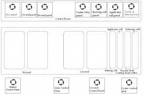
 Coating lines are very popular in industries such as plastics, paper-processing, steel and aluminium amongst others. One project Optima has been involved in was control system design and build for a coating head, part of an extruder coating line. Below you can find a diagram and full description of the control system functionality for this job.
Start-up Sequence
The Thread In pushbutton is pressed from the Main Desk or Coater Desk Once the start alarm has ceased the run pushbutton is pressed, this increases the line speed to 50mpm. Once all rollers are in run mode the line can be speeded up. When the machine is running the Transfer, Applicator and Metering rolls follow Speeds are selected via potentiometers on the coater desk.
Unwind
The two Unwind spindles operate in closed loop centre wind with dancer tension control.
Unwind Splice
Both a manual and automatic splicing function is available on the unwind. The splice arm operates in both the under-wind and over-wind mode. Splicing is initiated from the Unwind Operator Panel. During automatic splice the unwinds are turreted into an initial position using an AC motor. This position is detected using a proximity sensor mounted on the fixed unwind stand. The splice arm is raised into position and then the unwind is turreted until the photo cell mounted on the splice arm detects the incoming reel. A layon arm is used to calculate the diameter of the incoming reel so that the correct speed can be used for splicing. An additional encoder is added to the unwind turret for use in calculating the reel diameter. Once the splice is complete, initiated by a switch on the operator pendant, the outgoing reel is stopped and the splice arm is returned to its lower position.
Coater
The Coater comprises of:
- Backing Roll and S-Wrap operate in closed loop with load cell tension control. The required tension is entered via a pot on the Coater Control Desk.
- Applicator Roll: The required speed is entered via a pot on the Coater Control Desk.
- Transfer Roll: The required speed is entered via a pot on the Coater Control Desk.
- Metering Roll 2: The required speed is entered via a pot on the Coater Control Desk.
Rewind
The two Rewind spindles operate in closed loop centre wind with load cell tension control. The required tension and taper tension are entered via pots on the Rewind Control panel. An Operators pendant is used to jog the rewind spindle so that shrink wrap can be applied to the full roll.
Rewind Splice
The splice arm only operates in under-wind mode. Splicing is initiated from the operator panel
During automatic splice the rewinds are turreted into position using an AC motor. This position is detected using a proximity sensor mounted on the fixed rewind stand. The splice arm is lowered into position so that it almost touches the incoming reel. Once the splice is complete the outgoing reel is stopped and the splice arm is returned to its back position.
Would you like to know more about other control system projects we have completed on coating machines? Please, email us at info@optimacs.com or call us on
+44 (0)1254 27 28 29

