 Slitting machines are widely used to cut soft materials such as paper and plastic films. Slitters have winding and rewinding sections that present a challenge to the machine’s control system. Optima has completed a number of slitting machine upgrades. Below you can find descriptions of both the machine’s working principles and the control system philosophy employed by Optima for one particular project.
Rewind Recipe System
The recipe system is based on Rockwell Automation’s RS view Scada package running on a standard PC.
System Configuration
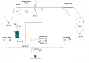
The slitting machine consists of rear (internal rewind) and front (external rewind) arms. The position of the rear and front arms is controlled by individual linear potentiometers. These potentiometers are used to control the position of the arms and also calculate the diameter of the cheeses (reels). The lay-on/lay-off pressure on the arms is adjustable. The present controls are used to manually set the various winding parameters. A PLC system is fitted to enable up to recipe’s to be used to automatically profile the winding parameters.
The old operating system is used to control the front and rear winder tensions, taper tensions, lay-on and lay-off pressure by the use of the potentiometers mounted on the operator control panel.
The existing controls are kept and used for manual control of the winder parameters. These controls now work independently from the new PLC system, with no change in the functionality from their original conception.
The new PLC system is used to profile the tension, taper tension, lay-on, and lay-off parameters. A manual/automatic selector switch allows the operators to run the machine in either mode. A set of manual/automatic changeover relays is used to switch between these modes.
The existing I/P driver cards are retained and used with either the existing manual or new automatic 0–10VDC reference signals.
A Rockwell Automation 6185 industrial monitor 17″ TFT resistive touch-screen is used to input and display the winder profiles.
The PLC system monitors when the Unwind reel is unloaded. The operators are required to confirm that either the existing or new recipe selected is compatible with the Unwind product they are about to run. The machine does not start until the recipe is accepted.
A suitable PC interfaced with the 17” monitor runs the Rockwell Automations RS View Scada software. This PC is mounted in the new control cubicle.
Control Cubicle
To allow for the upgrade of the Siemens S5 PLC we installed an additional control cubicle adjacent to the existing machine control cubicles. This cubicle is now used to house the PLC for use with the recipe system and to replace the S5 PLC.
Replacement Of Siemens S5 PLC
Control Cubicle
The existing S5 PLC is replaced with Allen Bradley remote I/O modules to be located in the control cubicle that presently contains the S5 PLC. To allow upgrade to be completed with minimum disruption to production it is recommended that the following additional work be undertaken to allow a phased commissioning of the machine.
Install a terminal rail and the Allen Bradley PLC equipment pre-mounted on a backplate in close proximity to the S5 PLC. This allowed the PLC inputs and outputs to be connected to both the S5 and the Allen Bradley remote I/O units. This enabled the Allen Bradley software to be commissioned in stages, switching back to the S5 PLC to allow production to continue until the commissioning is completed.
Unwind Section
Driven Unwind
Optima fitted a new DC motor, gearbox and pneumatically released brake (E-stop) on the unwind stand. We supplied a mechanical drive assembly and a new drive control cubicle containing a Parker SSD 590+ Integrator series drive and associated control equipment. In addition, a new Honeywell ultrasonic diameter sensor for measurement of the Unwind reel diameter is supplied and fitted.
The existing analogue diameter calculation and PID cards were prone to analogue drift. Fitting a new 590+ controller allowed the diameter and PID control to be done in the 590+ software blocks. The software configurations in the 590+ are more reliable and are not prone to analogue drift; this results in a stable repeatable control loop.
The control of the web tension using a driven unwind improved the performance of the unwind. The areas that significant improvements occured are listed below.
a) The performance during acceleration is improved. Because the driven unwind can drive the roll during acceleration the dancer and the tension in the web is controlled during acceleration. This results in significantly reduced deformation of the web i.e. stretching and shrinkage.
b) It is also possible to reduce the acceleration time with a driven unwind compared to a braked unwind.
c) The performance during deceleration is improved. The response of the control loop is faster with a driven unwind and the control of the web tension with large rolls and high inertia is improved.
d) It is now possible to reduce the deceleration time with a driven unwind, this is due to the ability of the DC motor to produce the required torque to control the web tension. A braked unwind would not control the tension in the web with the same degree of accuracy. The decrease in the decelerate time results in less scrap product being produced.
e) The control of the web tension during steady state running is improved by using a driven unwind compared to a braked unwind.
f) There are energy savings associated with a driven unwind. The unwind DC motor is mostly in a regenerative condition. The generated power from the motor is returned to the mains supply, helping to reduce energy consumption.
Would you like to know more about other control system projects we have completed on slitting machines? Please, leave us a short message here and we will send you additional information within 24 hours!
