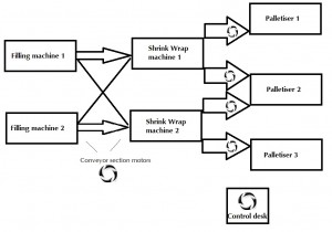
 Conveyors are widely used for material handling and speeding up the production process. Optima has been involved in conveyor controllers upgrade projects on a number of occasions. The diagram below depicts one such project for a paint palletising line.
The states of diverter bar switches signal the required routes. Once started, all used conveyor sections run.
If a conveyor section or the shrink wrapper on a route goes faulty or a missing lid is detected, the filling machine and all of the conveyor sections upstream of the fault are stopped. Downstream sections continue to feed the palletiser.
If, on a route, no tin is detected at the ‘jam detection’ photocell and there is a fault with the palletiser, tins are transported as far as possible until the first tin reaches the photocell. At this point the conveyor feeding the palletiser stops.
If, on a route, a shrink wrapper is being used and there is a palletiser fault, the in-feed conveyor to the shrink wrapper is stopped and the filling machine continues running until all conveyor sections upstream of the shrink wrapper in-feed are backed up. At this point the filling machine and all conveyor sections on this route stop until the palletiser fault is cleared.
If on a route, a shrink wrapper is not being used and there is a palletiser fault, as soon as a tin is detected at the jam detection photocell, the filling machine and entire route are stopped until the palletiser fault is cleared.
Conveyor section photocells (not shown on the diagram) are used to detect the presence of tins to create a buffering system. These photocells detect the presence of a tin for more than 5 seconds. When this occurs, the motor of the conveyor section on which this photocell is mounted is switched off until the downstream conveyor section is clear.
The conveyors self empty whenever a filling machine has finished production.
When a shrink wrapper is not to be used (i.e. for large tins) automatically actuated diverter bars divert the flow of tins around rather than through the shrink wrapper.
Optima was involved in replacing the main enclosure containing the PLC, associated control equipment, operator HMI and emergency stop controls. For other conveyor projects, AC/DC drives have also been upgraded.
The following control system design stages were within the scope of this project:
Project Specification Control system design Electrical circuit diagrams PLC software Enclosure build Full functional test of both hardware and software elements.
Would you like to know more about other control system projects we have completed on conveyor machines? Please, email us at info@optimacs.com or call us on +44 (0)1254 27 28 29

