 Belt machines are typically used for grinding and finishing different materials. Optima upgraded a belt machine that operates in five modes:
- Loading
- Casting
- Grinding
- Edge Trimming
- Unloading
Loading
To load the machine the top roll is moved down towards the top roll supports these are situated on the casting beam on either side of the top roller. Once the top roll is on its supports the roll can then be uncoupled at both ends. When both sides of the top roller are uncoupled, the top roller screw mechanism can be raised until it is out of the way. The pit jack should be in its up position supporting the casting beam at the unload end. The cell work frame can then be unbolted and moved away from the load / unload end of the machine. The gate at the load / unload end of the machine can now be swung fully open. Once the gate is fully opened the pit jack can then be lowered, when in the lowered position the machine is ready to load. An overhead crane is then used to place the base cloth over the top and bottom rolls. When the base cloth is in place the pit jack will be raised to support the casting beam and allow the gate to be closed. Once the gate has been closed and bolted, the top screw mechanism can be driven back down to the top roller. The top roller can now be coupled together at both ends. The machine is ready to run.
Casting
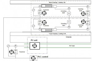
The casting operation is carried out using a front casting cell and rear casting cell that traverse together on the casting beam across the base material casting molten polymer onto the base material. To cast the polymer tanks are prepared and heaters associated with casting turned on. The casting cells and PU traverse are lined up manually using controls on the HMI. The PU transfer pumps are started at the required speed to feed the required volume of polymer onto the backing material. The top roll is started and then the casting cells (casting belts and traverse) and PU are started, they traverse at a set speed along the belt.
Grinding
Once the casting operation is complete the casting cells are replaced with the grinding cells and the belt surface is then ground to produce the required surface finish. The grinding operation is carried out by a front grinding cell and rear grinding cell which traverse together across the casting beam, both cells have driven abrasive belts. The amount of grinding cell cut is set using a cell gap value entered on the HMI, an inductive sensor provides feedback of the cell gap and a servomotor with associated linear actuator is used to control the position of the front cell. The abrasive belts pass over upper and lower rolls.
Edge Trimmer
After loading a new belt and setting up the tracking, and after completing grinding, the edges of the belt can be trimmed. To do this a cutting tool is used. The cutter is on the same rail as the grinding/casting cells, and is moved into position by sliding it along the rail by hand. Once in position the cutter motor is started and stopped via a detachable push-button box, or via the HMI.
Unloading
To unload the machine the overhead crane is attached to the finished belt. When the crane has the belt in position the top roll is moved down towards the top roll supports, these are situated on the casting beam on either side of the top roller. Once the top roll is on its supports the roll can then be uncoupled at both ends. When both sides of the top roller are uncoupled, the top roller screw mechanism can be raised until it is out of the way. The pit jack should be in its up position supporting the casting beam at the unload end. The cell work frame can then be unbolted and moved away from the load / unload end of the machine. The gate at the load / unload end of the machine can now be swung fully open. Once the gate is fully opened the pit jack can then be lowered, when in the lowered position the machine is ready to unload. The overhead crane is then used to remove the belt from the top and bottom rolls. When the belt has been moved clear of the machine, another base cloth can be loaded or the pit jack is raised to support the casting beam and allows the gate to be closed. Once the gate has been closed and bolted, the top screw mechanism can be driven back down to the top roller. The top roller can now be coupled together at both ends. The machine is ready to run.
The belt machine control system designed and upgraded by Optima comprised of:
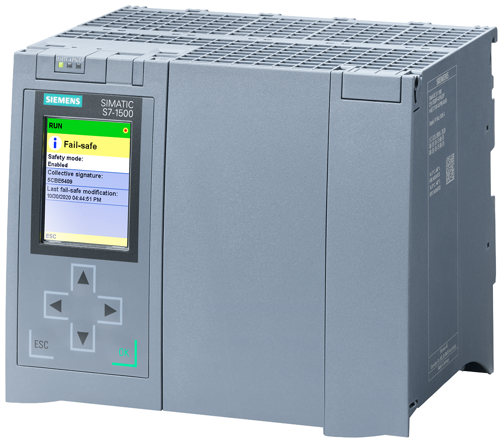
- Siemens S7-300 PLC.
- ET200S Remote IO distributed in control boxes around the machine.
- SIMOTION drives controlling servomotors with control units and SIMOTION D controllers where required to achieve the specified functionality.
- Micromaster drives controlling AC motors.
- Most operator controls were provided on a Human Machine Interface (HMI) located on the PU operator panel. This HMI used WinCC Flexible.
Would you like to know more about other control system projects we have completed on belt machines? Please, leave us a short message here and we will send you additional information within 24 hours!
