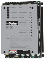
All 514

The range of 514C Series regenerative converters, with single phase AC supply,
offers full four-quadrant control of wound field or permanent magnet DC motors.
It is ideal for applications requiring accurate braking of high-inertia loads or their
fast and precise deceleration. 514C Series and its non-regenerative version 512C
have been designed to offer the ideal solution for speed control of single and multimotor applications.

Link to 514C DC Manual

Features of the 514C drives are as follows:

Jumper-selectable single phase input voltage 110//120 or 220//240 or 380/415V ±10%
Linear current feedback allowing accurate torque
Zero speed or zero set point relay driver output – 24Vdc
Total setpoint output
Stall detection and trip
Field bridge suitable for UK or continental voltages
Overload capacity 150% of nominal current for 60s
Adjustable maximum current level
Adjustable maximum and minimum speed

Adjustable I.R. compensation (for armature voltage feedback speed control)
Adjustable speed stability
Independent control of speed ramp, both up and down from 0-40s
Indication of mains supply on, stall trip and overcurrent trip
Switch selectable current calibration
Switch selectable Armature/Tacho generator feedback
Buffered 0-10V output for a speed reference or meter
Buffered 0-7.5V output for a current meter (7.5V = 150%)

Recent Posts

Safety Scanner Issues and EN999

Optima were recently asked to advise on a safety guarding application for one of our customers. 

There had been a number of false trips of the laser scanner causing the machine to stop. A plastic chain ‘barrier’ had been fitted as a temporary measure with instructions to operators to not breach the barrier whilst the machine was running. 

The customer naturally wanted this rectifying as soon as possible. Optima carried out a service visit to site.

On the site visit, our engineer noted that the scanner was showing a code which indicated that the front screen required cleaning.

 Once the screen was cleaned thoroughly the scanner did not show any faults or errors and was in normal run mode.


Further checks on the original software were made to ensure the scanner configuration met the requirements of the safety guarding application. 

The diagrams to the left show the Warning Field configuration (Yellow) and the Protective Field (Red). Both of these were confirmed to be operational. 

The warning field causes the klaxon to operate but does nto stop the machine. The protective field causes an emergency stop of the machine.

We did find some concerns that needed addressing.

1. None of the scanner safety circuit had been documented on any drawings.

2. Non-compliance with EN999 ‘Safety of machinery. This defines the positioning of protective equipment in respect of approach speeds of parts of the human body’. It includes a formula to be used to calculate the distance from a hazard that a safety zone must be triggered. 

Based on the stopping times of the machine, the scanner was placed too close to the machine to be effective in an emergency.

We are working closedly with our customer to assist them with this application and help them achieve a safe and effective solution to this.

If you need any support with safety applications or other upgrades, please get in touch.. 

  1. Parker SSD Microtach Replacements Leave a Reply
  2. Accelerate your digital and sustainability transformation at Siemens Transform 2024 Leave a Reply
  3. Optima’s Siemens Solution Partner Accreditation for 2024 Leave a Reply
  4. Cloud-based data dashboards Leave a Reply
  5. Siemens Transform Event Leave a Reply
  6. Rockwell Extended Warranties Leave a Reply
  7. S88 Solution Solves Obsolescence Issue Leave a Reply
  8. Up to 5 Years Warranty as Standard on our Motor and Drive Upgrades with Siemens Leave a Reply
  9. Optima achieve accreditation by Avetta for supplier competency Leave a Reply