 Cutting machines require absolute precision and control in order to produce exactly the same sheets of material (most often metals) without any defects. Optima has completed a number of complex projects involving control system design and upgrades for rotary shears.
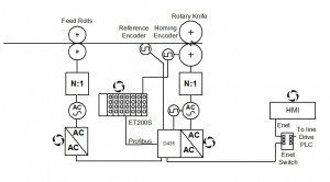
The diagram below shows the control system principles employed by Optima’s control engineers for one rotary shear project.
The shear is controlled using a high performance brushless servomotor coupled to the shear blade using a low backlash servo gearbox. The servomotor is controlled using a Siemens Simotion controller and Sinamics servo drive.
The infeed nip rolls are controlled using a closed loop vector controlled inverter drive operating in torque control. This provides a controlled infeed strip tension to the shear blades.
A measuring wheel linked into the servo motion controller is used to provide a continuous measurement of sheet position to the motion controller which using this information calculates the relative shear positions and hence cut points.
The shear speed matches the line speed whilst the cut is being made and then ramps to a different speed which is dependent on the distance between cuts.
A programmable encoder is used to identify blade position for homing of the shear blade.
To facilitate easy communication, the shear control system Simotion controller communicates with the line drives control PLC using an Industrial Ethernet network.
There is a colour HMI (TP177PN 5.7” with Ethernet) for operators to enter operational parameters and for some diagnostic facilities. This allows: start/stop; cut length; infeed tension and shear status to be set and monitored when the shear is operated in stand alone mode.
A hardwired emergency stop and guarding system including self locking upstream and downstream knife and nip guards ensure safe operation of the shear. This is linked into the line emergency stop system. Safety category 4 (EN 954-1).
A maintenance pendent is supplied for adjustment / replacement of the shear blade. This allows shear blade jogging forward and reverse at very slow speed to enable accurate blade measurements and adjustments. Safety guards may be opened to gain access to the shear blades whilst the pendent is connected but the machine does not run in auto until both upstream and downstream guards are closed and the pendent has been removed
All electrical equipment is housed in a freestanding enclosure located adjacent to the shear frame, approx dims. 1200mm (w) x 2100mm (h) x 500mm (d).
Would you like to know more about other control system projects we have completed on rotary shear machines? Please, leave us a short message here and we will send you additional information within 24 hours!
