All Parker SSD Link

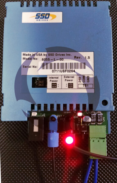
SSD LINK is a distributed control system designed for the management and control of motor drives and associated equipment.

Optima have over 25 years experience in designing and commissioning LINK drive systems. Our largest ever project contained a combination of over 125 AC and DC Drives on one network.

If you need help on your LINK system either with service, spares or support – we can help!

The major advantage with link is that all the modules are connected by a high speed fibre optic cable network, which eliminates network signal noise and creates a very robust automation platform.

The largest system we have supplied used two Link racks in tandem on a large paper coating line (Link 2 Rack Panel Shown Below).
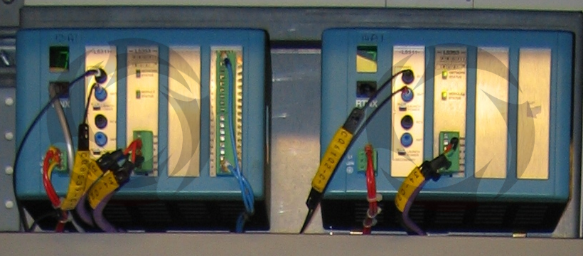
LINK hardware mostly comprises:

  • Drives connected directly to motors
  • Operator stations presenting information to / commands from the operator
  • Analog I/O modules
  • Digital I/O modules
  • Serial I/O modules
  • Gateway modules for PROFIBUT, ControlNET, Ethernet

The latest version of Link is an Ethernet-based LinkNET system which Optima can also support and upgrade your existing fibre optic network to the latest LinkNET hardware.

Recent Posts

Safety Scanner Issues and EN999

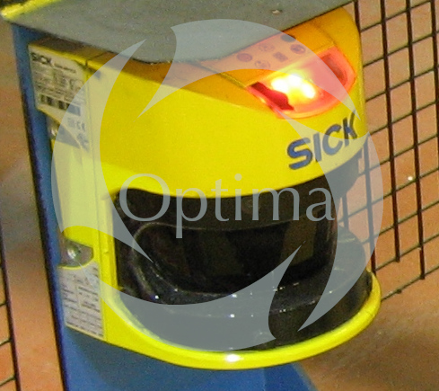
Optima were recently asked to advise on a safety guarding application for one of our customers. 

There had been a number of false trips of the laser scanner causing the machine to stop. A plastic chain ‘barrier’ had been fitted as a temporary measure with instructions to operators to not breach the barrier whilst the machine was running. 

The customer naturally wanted this rectifying as soon as possible. Optima carried out a service visit to site.

On the site visit, our engineer noted that the scanner was showing a code which indicated that the front screen required cleaning.

 Once the screen was cleaned thoroughly the scanner did not show any faults or errors and was in normal run mode.


Further checks on the original software were made to ensure the scanner configuration met the requirements of the safety guarding application. 

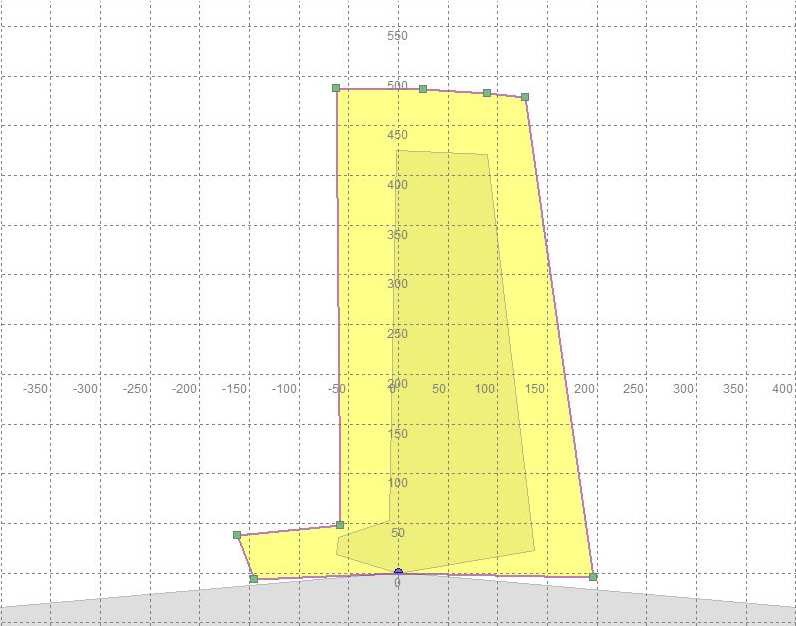
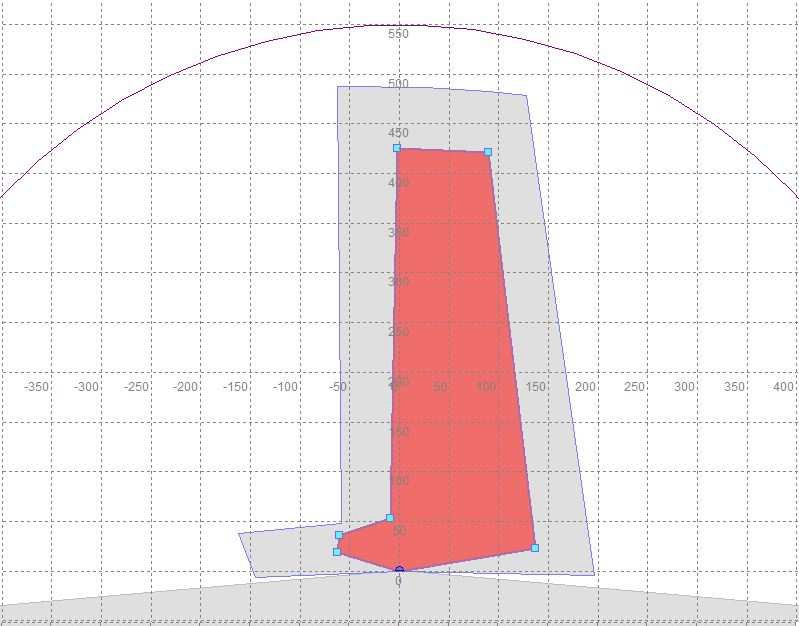
The diagrams to the left show the Warning Field configuration (Yellow) and the Protective Field (Red). Both of these were confirmed to be operational. 

The warning field causes the klaxon to operate but does nto stop the machine. The protective field causes an emergency stop of the machine.

We did find some concerns that needed addressing.

1. None of the scanner safety circuit had been documented on any drawings.

2. Non-compliance with EN999 ‘Safety of machinery. This defines the positioning of protective equipment in respect of approach speeds of parts of the human body’. It includes a formula to be used to calculate the distance from a hazard that a safety zone must be triggered. 

Based on the stopping times of the machine, the scanner was placed too close to the machine to be effective in an emergency.

We are working closedly with our customer to assist them with this application and help them achieve a safe and effective solution to this.

If you need any support with safety applications or other upgrades, please get in touch.. 

  1. Parker SSD Microtach Replacements Leave a Reply
  2. Accelerate your digital and sustainability transformation at Siemens Transform 2024 Leave a Reply
  3. Optima’s Siemens Solution Partner Accreditation for 2024 Leave a Reply
  4. Cloud-based data dashboards Leave a Reply
  5. Siemens Transform Event Leave a Reply
  6. Rockwell Extended Warranties Leave a Reply
  7. S88 Solution Solves Obsolescence Issue Leave a Reply
  8. Up to 5 Years Warranty as Standard on our Motor and Drive Upgrades with Siemens Leave a Reply
  9. Optima achieve accreditation by Avetta for supplier competency Leave a Reply